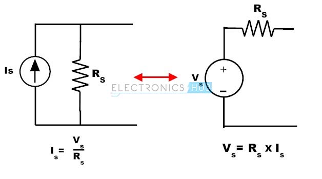
The voltage and current source are mutually transferable or in other words the source transformation ie. Now to convert this current source into voltage source simply multiply the values of the current source and its internal resistance IR and place this resistance R in series with this current source.
 Source Transformation
Source transformations are implemented using Thévenins theorem and Nortons theorem.
Voltage source to current source transformation. Where V s is the terminal voltage of the source and R s is the internal resistance of the voltage source. Suppose we have the following voltage source shown on the left side in the diagram and we want to transform it to a current source on the right side. From the above discussion a voltage source can be converted or transformed into a current source by interchanging a series resistor to parallel as shown in figure.
Are treated as a current source or an output produce by the direct or alternating voltage source is called direct and alternating current source respectively. Source transformation technique is mainly based on __________ law. Using source transformation the voltage source in series with a resistor to be replaced by a current source in parallel with the same resistor and vice versa.
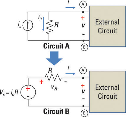
R P R L v RL I S i RL 25 mA 2 k. Source transformation is a method used for circuit simplification by replacing the voltage source with its equivalent current source or replacing the current source with its equivalent voltage source. R S R L v RL V S i RL 5 V 2 k.
For ideal electrical sources losses will be zero. The semiconductor devices like transistors etc. It is easy to show that they are indeed equivalent.
Therefore this technique will convert voltage source into equivalent current source and current source into equivalent voltage source. Such a voltage source is called an Ideal Voltage Source and have zero internal resistance. Source Transformation zEquivalent sources can be used to simplify the analysis of some circuits.
This current source transformation calculator transforms the above circuit with a current source and resistor in parallel into the equivalent circuit with a voltage source with a resistor in series. And the process of converting from one source to another is called source transformation. Find the internal resistance of the voltage source and keep this resistor in parallel with a current source.
Voltage source and Current Source. I_sfracV_sR_s In source transformation the Voltage source V s is converted into Current Source. Source Transformation is a technique to convert one kind of source into other.
In this case also the direction of new voltage source is same as that of the current source. Conversion of Voltage Source to Current Source. Practically an ideal voltage source cannot be obtained.
The value of the voltage source is calculated according to ohms law V IR voltage current resistance. A source transformation is the process of replacing a voltage source v s in series with a resistor R by a current source i s in parallel with a resistor R or vice versa. This kind of transformation is required to solve circuit network.
There are two types of sources. VRL RL RL RS VS. But it is often seen that both the voltage source and current source exist in the same circuit.
ZA current source in parallel with a resistor is transformed into a voltage source in series. An electrical source transformation or just source transformation is a method for simplifying circuits by replacing a voltage source with its equivalent current source or a current source with its equivalent voltage source. For nodal analysis we consider source currents to flow into a node.
A highly valuable byproduct of Thevenins and Nortons theorem is the technique of source transformation. In order to solve the circuit simply the current source needs to be converted to a voltage source or a voltage source to a current source. With the ease of Ohms Law the source is converted with the following formula.
So in this way we can inter-convert voltage and current sources easily as per our requirements. In general the concept of source transformation is an application of Thévenins theorem to a current source or Nortons theorem to a voltage source. Current-to-Voltage Source Transformation again Finally we can transform the dependent current source into a dependent voltage source with the value V frac15i_1 5 frac158 frac315i_18 V This will be in series with a frac158 Omega resistor and will have its positive terminal towards the right.
This transformation is clear by the diagram give below. ZA voltage source in series with a resistor is transformed into a current source in parallel with a resistor. Source Transformation Source transformation is a circuit analysis technique in which we transform voltage source in series with resistor into a current source in parallel with the resistor and vice versa.
Namely that the load behaves linearly citation needed and does not contain dependent voltage or current sources citation needed. From the point of view of the resistor R L the series combination of the voltage source and resistor R S gives the exact same result as the parallel combination of current source and resistor R P. The two circuits in Figure1 are equivalent provided they have the same voltage-current relation at terminals a-b.
A voltage source is a two-terminal device whose voltage at any instant of time is constant and is independent of the current drawn from it. Nodal analysis is a circuit-analysis format that combines Kirchhoffs current- law equations with the source transformationConverting all voltage sources to equivalent constant-current sources allows us to standardize the way we write the Kirchhoffs current-law equations. Voltage to Current Source Transformation.
Voltage to the current source and current to a voltage source can be done. However this means that source transformation is bound by the same conditions as Thevenins theorem and Nortons theorem.
Spurious output transitions can be suppressed by using positive feedback to create a hysteresis band. And a single output with the reference of ground 0v.
 Op Amp Variable Reference Voltage Electrical Engineering Stack Exchange
A comparator circuit compares two voltages and outputs either a 1 the voltage at the plus side or a 0 the voltage at the negative side to indicate which is larger.
Op amp reference voltage. Low Input Offset Voltage. The op-amp can be considered to be a voltage amplifying device that is designed to be used with external feedback components such as resistors and capacitors between its output and input terminals. It is a high-gain electronic voltage amplifier with a differential input and usually a single-ended output.
To allow the op amp to self-bias as well as voltage-buffer the reference diode the op amp used must have both input and output swings which include the amplifiers V pin potential. In other words the op-amp voltage comparator compares the magnitudes of two voltage inputs and determines which is the largest of the two. RC 6k01uF results in a few hundred Hz LPF whether you have an Op Amp or not but at least no overshoot on turn on.
Its one of the simplest possible op-amp circuits with closed-loop feedback. 30 to 35 V. A voltage-reference IC or a resistive divider can be used to generate a threshold voltage for comparator circuits.
The Op-amp comparator compares one analogue voltage level with another analogue voltage level or some preset reference voltage V REF and produces an output signal based on this voltage comparison. 8 min read A voltage buffer also known as a voltage follower or a unity gain amplifier is an amplifier with a gain of 1. The value of output depends on the difference between the two inputs.
In the circuit shown below the op-amp is ideal and Zener voltage of the diode is 25 volts. The net open-loop small-signal voltage gain of the op amp involves the product of the current gain h fe of some 4 transistors. Generally if you need a good reference we use LDOs or bandgap zeners but if your Vcc is stable within 08V tolerance spec just the R ratio is fine.
One voltage is called the reference voltage and the other is called the input voltage. Wide Power Supply Range. An operational amplifier op-amp has a well balanced difference input and a very high gainThis parallels the characteristics of comparators and can be substituted in applications with low-performance requirements.
An op-amp voltage buffer mirrors a voltage from a high-impedance input to a low-impedance output. Also at the voltage across each of the capacitors is zero The time in milliseconds at which the output voltage crosses 10 V is. In practice the voltage gain for a typical 741-style op amp is of order 200000 and the current gain the ratio of input impedance 26 MΩ to output impedance 50 Ω provides yet more power gain.
12 min read In the previous section we used an ideal op-amp to construct an op-amp voltage buffer which copies a voltage signal from a high-impedance input to a low-impedance output. When the LT1178 op amp enters the picture a free and constant bias current source is available the 30μA quiescent supply current of the op amp itself. If the op-amp is higher than the positive input reference voltage I want the output voltage to remain stable in positive voltage for Stack Exchange Network Stack Exchange network consists of 176 QA communities including Stack Overflow the largest most trusted online community for developers to learn share their knowledge and build their careers.
In the case here this potential is nominally 12V above ground by virtue of the reference diodes terminal voltage. This circuit can be used to translate a sensor. Contents hide 1 Introduction to comparator 11 design of voltage comparator with op-amp 111 design of voltage comparator with op-amp for Zero-Level Detection 112 design of voltage comparator with op-amp Non-Zero-Level Detection 1121 Effects of Input Noise on Comparator Operation Read More.
An op-amp has an inverting input - a non-inverting input. Op-Amp Voltage Reference A voltage divider or other reference element plus an op-amp can create a fixed or adjustable voltage reference. Design Description This design uses an inverting amplifier with a non-inverting positive reference voltage to translate an input signal of 1V to 2V to an output voltage of 005V to 495V.
Large Output Voltage Swing. OP AMP1 has its noninverting input internally tied to a fixed 25-V reference while OP AMP2 is independent with both inputs uncommitted. 10 Voltage Precision Over Temperature.
Which may not matter. 0 V to V CC - 15 V Input Common Mode Voltage Range Includes Ground. An op-amp can function as a comparator because it combines a differential input stage with very high gain.
It is a circuit which compares a signal voltage applied at one input of an op-amp with a known reference voltage at the other input. For the A grade especially tight voltage regulation can be achieved through low offset voltages for both operational amplifiers typically 05 mV and tight tolerances for the voltage reference 04 at 25C and 08 over operating temperature range. Fixed Output Voltage Reference 260 V.
LM10 IC consists of a precision reference an adjustable reference buffer and an independent high-quality operational amplifier. 210 µAOp-Amp V CC 50 V Medium Bandwidth Unity Gain. Op-amp uses voltage shunt feedback to provide stabilized voltage gain.
At the input unit step voltage is applied ie.